
Visualyse Interplanetary

The aim of Visualyse Professional is to be able to model as wide range of radio systems as possible. Until recently, a restriction has been that all stations, both transmit and receive, are located either on the Earth’s surface or in orbit around the Earth.
With increasing interest in missions to the Moon, Mars and other celestial bodies in the Solar System, Transfinite have been working on how to model these deep space systems.
This page describes in overview the new product, Visualyse Interplanetary, that will allow modelling of missions to and around the Moon and other planetary bodies.
For detailed technical information, pricing or if you have specific question please contact us at info@transfinite.com
Introduction
The objective of Visualyse Interplanetary is to extend the simulation ability of Visualyse Professional to allow:
- Modelling of stations around other celestial bodies including the Moon and Mars
- Enhance the geometric framework with a more detailed description of the Earth’s shape and rotation characteristics.
The update to the geometric layer of Visualyse Professional was an opportunity to include additional features, in particular:
- Modelling how the frequency at the receiver is altered due to Doppler shift
- a constellation collision prediction tool
- inclusion of the full TLE orbit prediction model.
These enhancements allow a wide range of new scenarios to be modelled, such as:
- Checking there'd be no issues with harmful interference from crewed missions to the Moon or Mars using 4G and 5G mobile systems
- Checking that missions to the Moon or Mars from one space agency would not cause harmful interference into those of another
- Using more detailed orbit models to predict satellite positions and antenna pointing angles during the satellite or Earth station coordination process.
Installation and Configuration
Visualyse Interplanetary uses a new set of overlays, which should be located in the relevant overlays directory. Note these overlays have an additional field in each of the XML files which defines the relevant celestial body. An example of the overlays is shown below:
It is also necessary to have access to one of the JPL ephemeris data files. This file is called something like: lnxm13000p17000.431
The first time that Visualyse Interplanetary is run it should be configured to point to this file using the menu option File | Solar System Settings. This will open the following dialog:
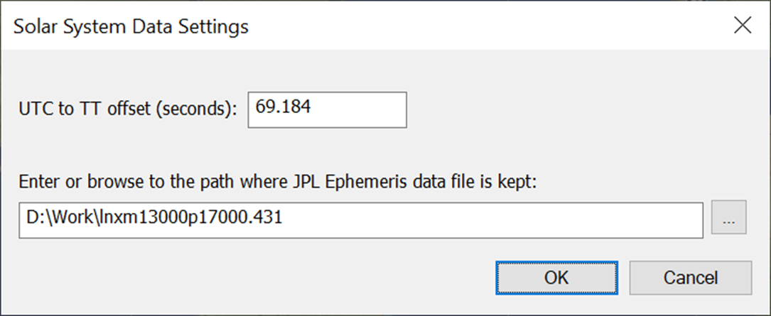
The UTC to Terrestrial Time (TT) offset allows the dynamic time to be defined relative to UTC.
Solar System Objects
Visualyse Interplanetary includes an additional list of objects to define the Solar System. This can be found under menu option Model|Solar System.
If the JPL ephemeris file is not specified, then Visualyse Interplanetary will work in legacy mode. In this case, the list will only contain the standard Visualyse Professional Earth which is a sphere of radius Re = 6378.145 km.
If the JPL ephemeris file is specified, then this will show the list of available celestial bodies:
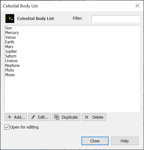
You can add, edit, duplicate and delete celestial bodies, allowing moons of the major planets and asteroids to be entered.
In the future, this could be extended to include the ability to import additional celestial bodies using a text file format (e.g. using orbit elements or J2000.0 state vectors).
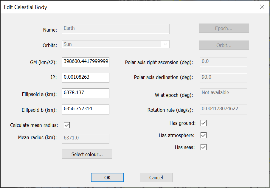
Each object can be viewed or edited using a dialog similar to this:
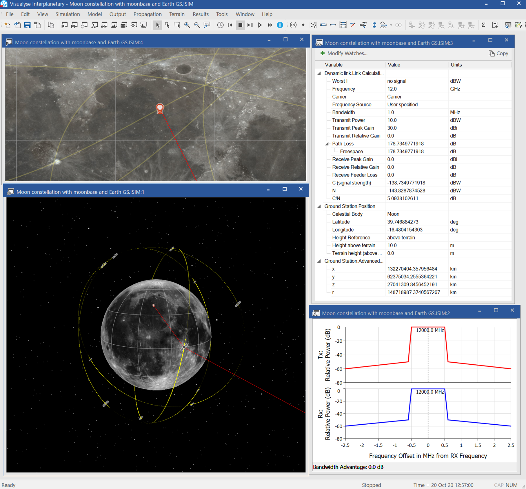
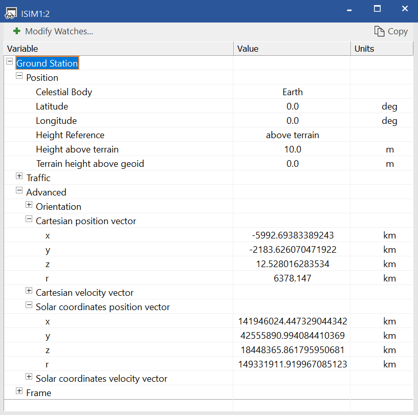
The watch window can also be used to view the configuration parameters and also calculated parameters:
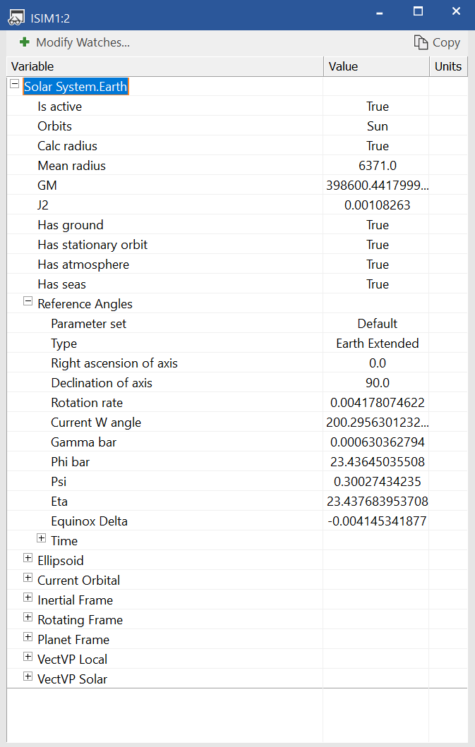
Note: that the Earth model in Visualyse Interplanetary is the standard WGS84 ellipsoid and that each object has defined what object it orbits.
Each celestial object has flags to identify if it has {Ground, Atmosphere, Seas}. This field is used to identify what types of station are permitted – so, for example, aircraft would not be permitted on the Moon.
File Save and Load
It is possible to save and load Visualyse Interplanetary simulations and load existing Visualyse Professional version 7.x files.
It is also possible to save Visualyse Interplanetary simulations to Visualyse Professional file format.
Station Types
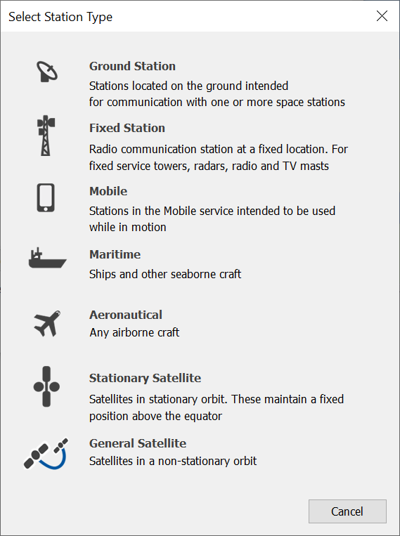
Station types have been relabelled to make them more generic and not Earth specific, as can be seen from the following dialog:
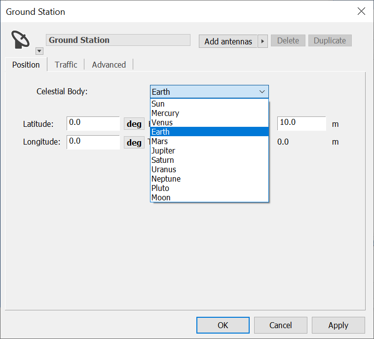
Each station dialog’s position page has an additional field to specify which celestial body this station is relative to. Here it is possible to select a new celestial body:
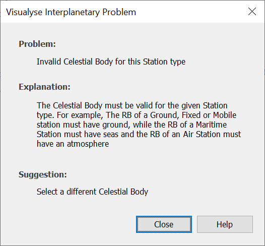
Note there are checks that the celestial body and station type are compatible. For example, selecting Jupiter here will result in the following error:
The location of each station is converted into position and velocity vectors relative to the selected celestial body.
These are then converted into a common J2000.0 coordinate system which is sun centred using the mean equatorial plane.
These two sets of vectors are visible in the watch window as follows:
Station Antenna Pointing
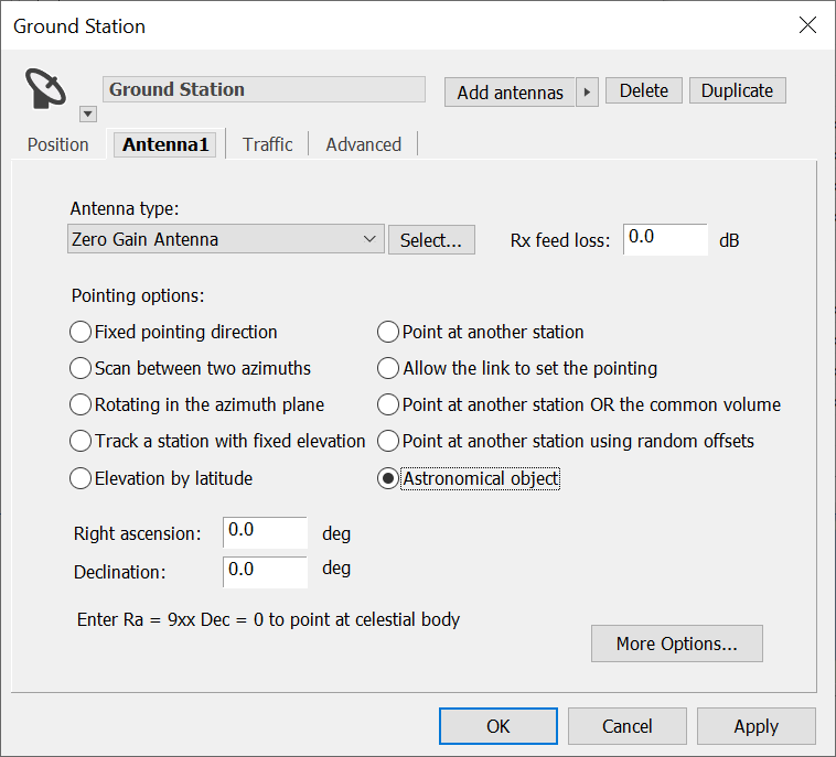
All the existing station antenna pointing methods continue to be applicable. There is an additional one which is to point at an astronomical object defined via its (right ascension, declination) angles, as can be seen here:
Note that the (azimuth, elevation) object has been changed to use a frame based approach and this has meant a simplification of the parameters for motion.
Station Reference Frame
In order to improve understanding of the underlying geometry, an additional object has been included and made visible, namely the reference frame for each station.
This defines how the station (azimuth, elevation) are calculated using three vectors as in the following diagram:
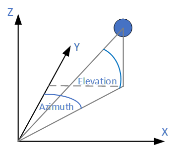
The three vectors of the reference frame are visible in the watch window.
Station Wizards
These are celestial body aware: in most cases this is set via the template station (or, where available, an existing station).
The preview window updates to reflect the celestial body in question e.g. default colour and whether to show country borders.
Note that when the Constellation Wizard uses an imported TLE file it is only applicable for Earth.
The TLE import also uses the full SGP4 / SDP4 orbit prediction code.
Import Tools
The following approaches have been used when updating the import tools:
- SRS import: has to be Earth
- Terrestrial import: has to be Earth
- Import non-GSO: select via the satellite properties
- FS import: has to be Earth
- TX import: additional field to define celestial body
- RX import: additional field to define celestial body.
Propagation Models
Most propagation models are only applicable for either terrestrial paths or Earth to space paths. The exception is free space path loss and the Extra Models (fixed loss and fixed loss / km) which are applicable for all paths.
Earth to space paths that go from Earth to another planetary body e.g. Mars would only use those models at the Earth end of the link.
It is possible that the in the future the P.526 diffraction model could be extended to work with other celestial bodies.
Terrain Data and Path Profiles
These will only work on terrestrial paths on Earth.
Links and Tracking Strategies
These should operate unaffected by the new geometric layer.
Time Dialog
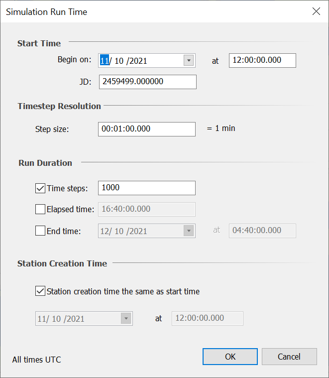
There have been minor changes to the time dialog:
- It is emphasized that all times are UTC
- There is an option to define the start time as a Julian date
- An option has been added to default the station creation time to be the start time.
The new dialog is shown below:
Map and 3D View
These have an additional tab to define parameters related to the celestial body:
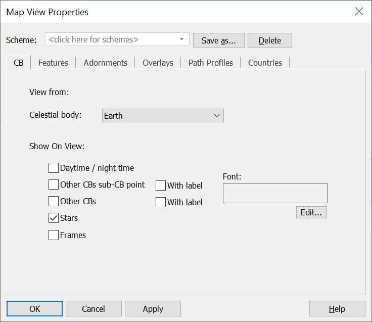
Only the stars has currently been configured, but the idea for the other is to show:
- Day and night hemispheres
- Which point on the selected celestial body has each other celestial body directly overhead, possibly with labels.
- For the 3D view, to show other celestial bodies as points, possibly with labels.
- For the 3D view, to show the station and/or celestial body reference frames.
Each of the overlays is checked to ensure it is compatible with the selected celestial body. Hence it is possible to specify these for multiple celestial bodies, but only the one(s) for the selected celestial body will be shown. This makes it easier to switch celestial body in the view without changing overlays:
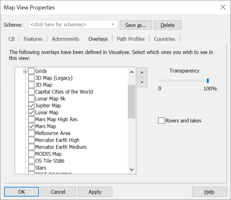
Countries etc. are only visible when the selected celestial body is Earth.
The 3D viewpoint option is now defined as “fixed inertial viewpoint”. The 3D view also shows links to other celestial bodies.
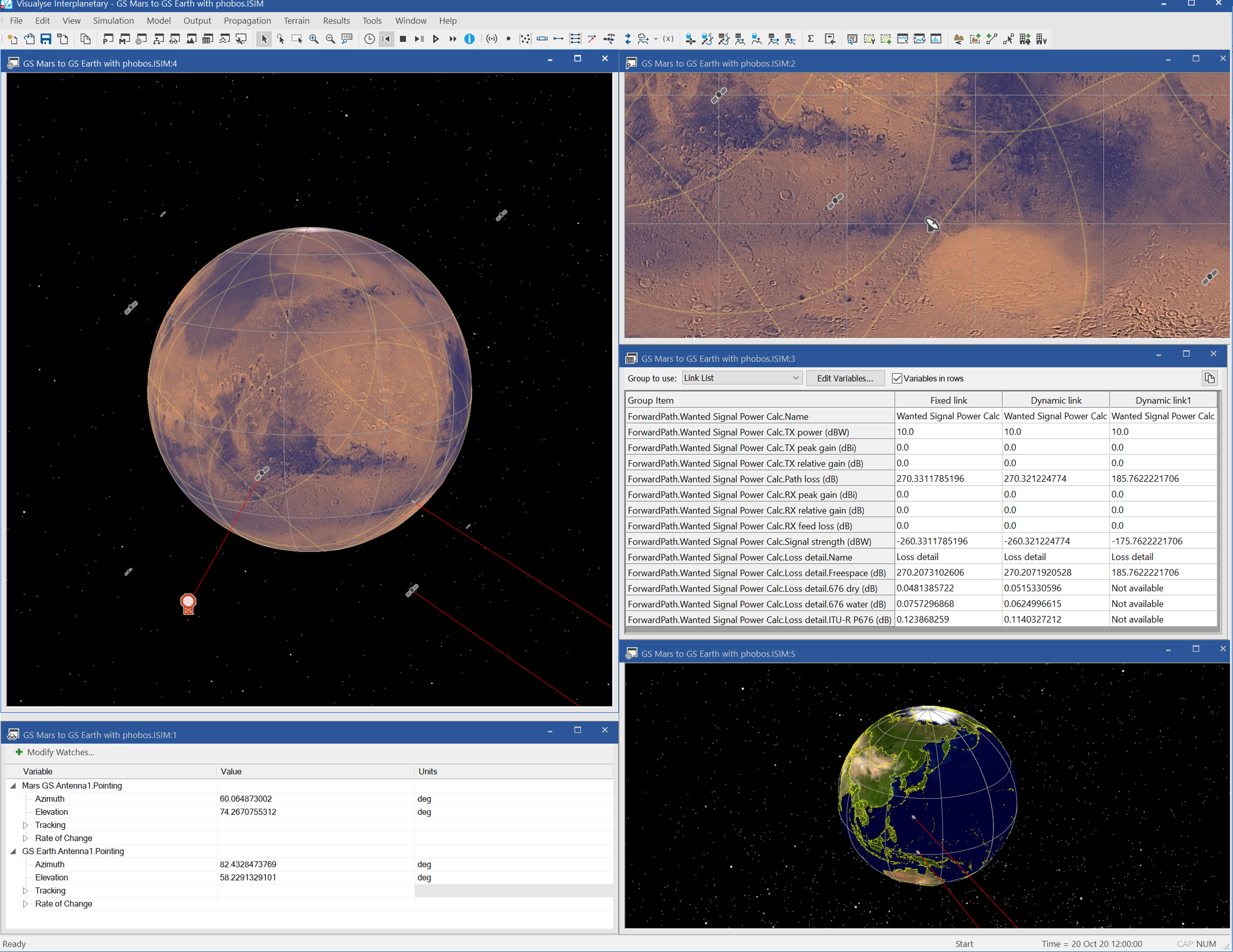
Example Simulation
This simulation shows a ground station on Earth selecting a satellite from a constellation around Mars. The constellation around Mars is also communicating with a lander on the moon Phobos.
Testing
We have undertaken three types of testing:
- Against existing simulations: this should give similar results but there could be minor changes due to differences in the geometric framework (e.g. spherical vs. ellipsoidal Earth)
- Against documents providing intermediate values, such as The Astronomical Almanac 2020
- Against external tools that can analyse interplanetary scenarios.
For the first of these, Visualyse Interplanetary includes a “legacy-mode” option that uses the same ECI coordinate frame as Visualyse Professional, allowing very close comparisons to be made.
For the last of these, a useful external tool to test Earth and interplanetary geometry was found to be the JPL Horizons web site: https://ssd.jpl.nasa.gov/horizons.cgi#results:
Current tests suggest results are within 0.01° of the values predicted by this web site. Other tests have suggested differences in positions predicted by Visualyse Interplanetary and other simulation tools of no more than a few metres or at most tens of metres.
There are some known differences. In particular, the Project Pluto code used predicts the position of celestial bodies centre of mass i.e. barycentre not planetary centre as per the JPL Horizons web site.
Libraries Used
Components from the following libraries are used by Visualyse Interplanetary:
Project Pluto: https://www.projectpluto.com/
Standards of Fundamental Astronomy (SOFA): https://www.iausofa.org/
Revisiting Spacetrack Report #3: https://www.celestrak.com/publications/AIAA/2006-6753/
Contact and further information
A demo version of Visualyse Interplanetary is available to download here.
If you would like more information, or have any questions, please do not hesitate to contact us