Abstract
There has been a growth in applications that require large amounts of data to be downloaded from satellites to ground, in particular from satellites operating in the Earth Exploration Satellite Service. For this reason, the World Radiocommunication Conference planned for 2023 has on its Agenda consideration of use of inter-satellite links in parts of Ku and Ka band. These bands area already used extensively by GSO and non-GSO satellite systems as well as terrestrial fixed links. It is therefore necessary to study the technical and regulatory issues involved in the operation of such systems. This Technical Note looks at issues relating to modelling these scenarios in the Visualyse Professional study tool.
Introduction
Recently there has been a significant increase in the number of Earth Exploration Satellite Service (EESS) satellites and payloads. This has led to a consequential increase in the requirement to download data from these satellites to ground for processing. It would be expensive to develop a ground infrastructure to handle all of this data, and so there is increasing interest in routing this over data relay satellites.
While there are bands for which there are allocations for the inter-satellite service (ISS), the demand for data transport could exceed the available spectrum, and so the World Radiocommunication Conference (WRC) in 2019 put on the agenda for WRC-23 Agenda Item (AI) 1.17 to study operation of inter-satellite links in various parts of Ku and Ka band, potentially under existing allocations of the fixed satellite service (FSS).
This Technical Note (TN) describes how to model some of these scenarios in Visualyse Professional.
AI 1.17 and Resolution 773
AI 1.17 resolves that WRC-23:
determine and carry out, on the basis of ITU-R studies in accordance with Resolution 773 (WRC-19), the appropriate regulatory actions for the provision of inter-satellite links in specific frequency bands, or portions thereof, by adding an inter-satellite service allocation where appropriate;
Resolution 773 gives more information, including the relevant frequency bands as being:
- 11.7 - 12.7 GHz
- 18.1 - 18.6 GHz
- 18.8 - 20.2 GHz
- 27.5 - 30.0 GHz.
Related to these frequency bands, it invites the ITU-R Radiocommunications Sector to:
- Develop the technical and operating characteristics of different types of space stations
- Study the technical and operational characteristics for transmissions between space stations
- Study sharing and compatibility between satellite-to-satellite links intending to operate between space stations and current and planned stations of the FSS and other existing services allocated in the same or adjacent frequency bands with a view to ensure protection of the primary services
- Develop, for different types of space stations, the technical conditions and regulatory provisions for satellite-to-satellite operations including new ISS allocations, as appropriate.
The lead Working Party (WP) for this AI is WP 4A with involvement from WP 3M, WP 4B, WP 4C, WP 5A, WP 5B, WP 5C and WP 7B.
Initial Concepts at WP 4A
There have been a number of inputs into WP 4A that address AI 1.17, and some of them discuss the concept of the cone of operation, as shown in the figure below:
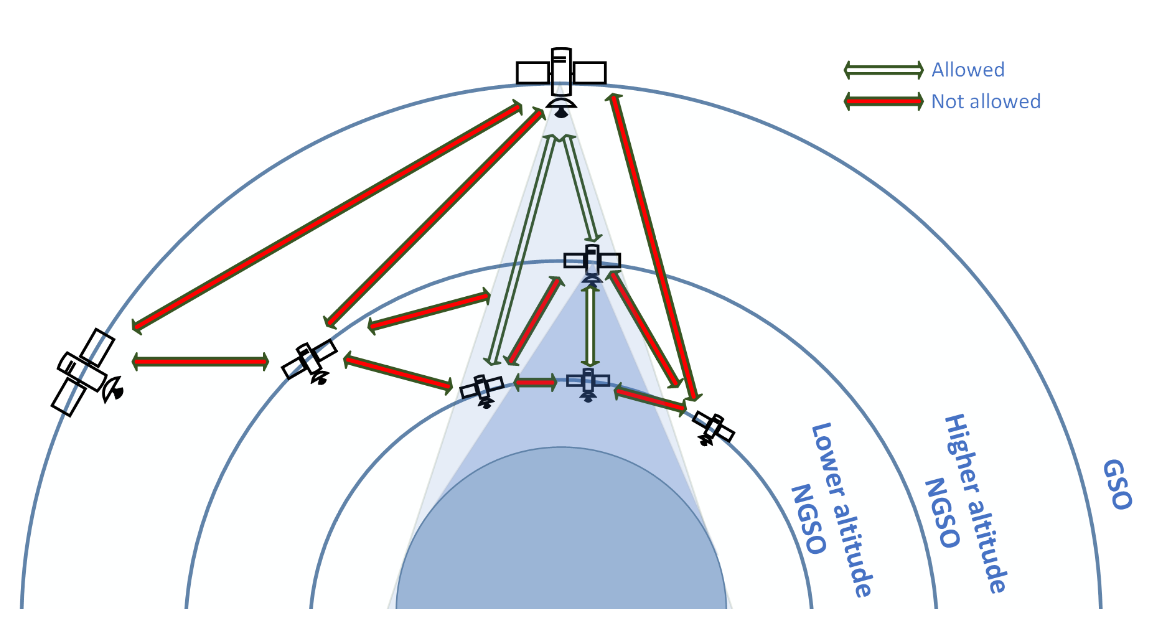
The idea is that if the non-GSO user terminal (UT) (e.g. the EESS satellite that needs to transmit data to ground) operates within the existing cone of operation of the Geostationary Satellite Orbit (GSO) or non-GSO satellite, then it will appear from an interference perspective as a ground terminal, and similarly in the reverse direction.
For example, consider two GSO satellites, one communicating with a non-GSO UT and another victim adjacent on the GSO arc. If the non-GSO UT transmits with EIRP such that the PFD at the victim GSO satellite is unchanged, then the interference environment for that GSO satellite should be similar.
This concept can be conceived as an extension of the regulatory framework around Earth Stations in Motion (ESIM) which operate within the constraints for ground based, static ES.
However, it is worth nothing that:
- the geometry of operating in non-GSO orbit is significantly different to that from operating within the Earth’s atmosphere
- there were significant difficulties in getting agreement in use of ESIMs, for example to ensure protection of fixed service links
It is therefore necessary to undertake studies as identified by Resolution 773 to consider this and potentially other operating models.
This technical note shows how to model one of these options in Visualyse Professional, namely a non-GSO UT communicating with a GSO satellite interfering with a victim non-GSO network.
The TN also considers other victim services including stations in the fixed service or HAPS.
Sharing with non-GSO System
Baseline Simulation
This section describes the baseline simulation used in this TN. Note these were selected to show aspects of simulation and modelling rather than typical parameters of actual systems in this band.
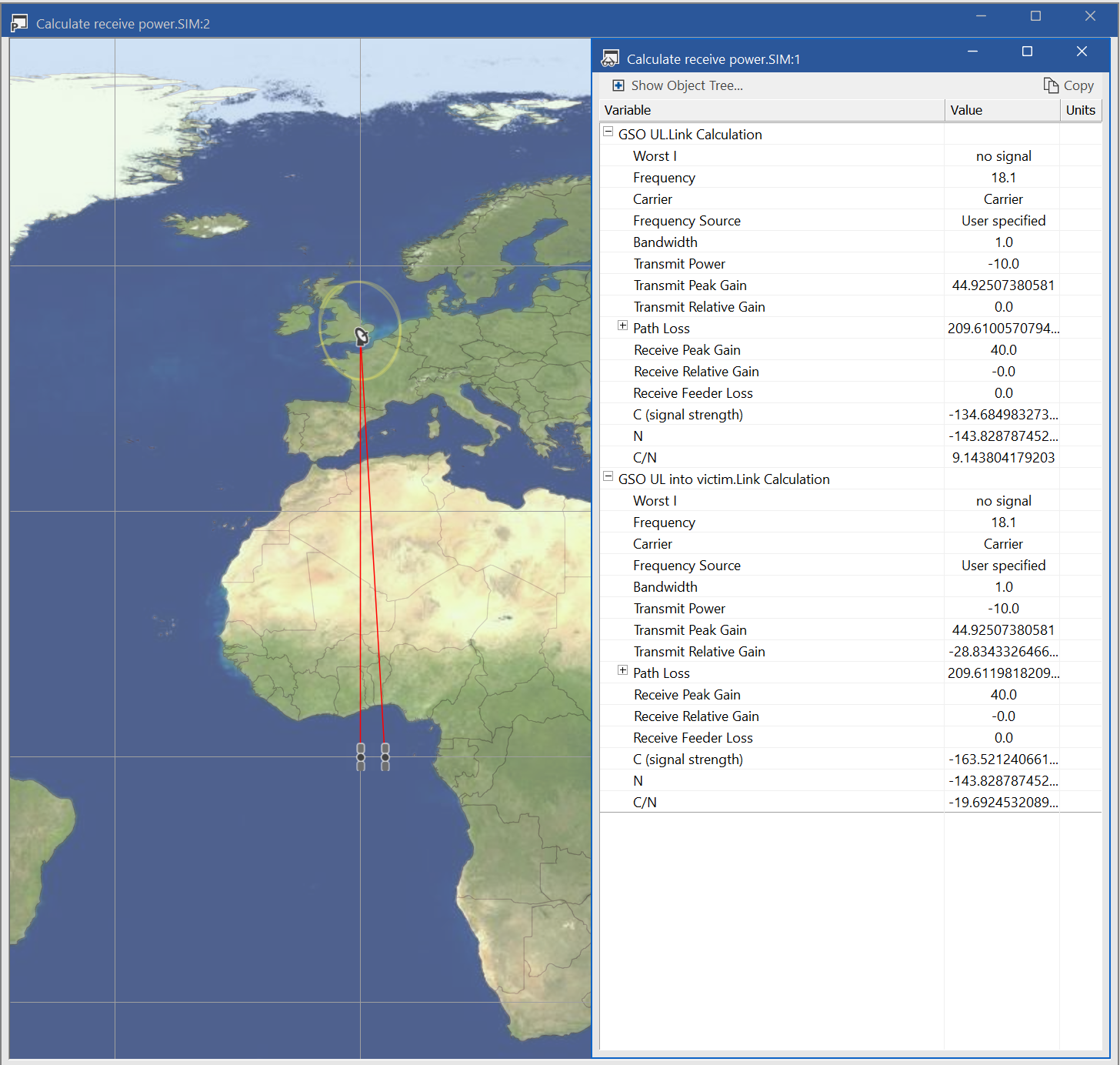
The basic idea was to create a GSO uplink (UL) from an ES to a GSO satellite and identify what the interfering signal strength would be at an adjacent satellite. This would then be used as the “acceptable” interference in the main simulation. The main parameters were:
| Frequency: | 18.1 GHz |
| ES dish size: | 1.2 m |
| ES gain pattern: | Rec. ITU-R S.580 |
| GSO peak gain: | 40 dBi |
| GSO gain pattern: | Rec. ITU-R S.672 |
| EIRP: | -10 dBW/MHz |
| Resulting C/N: | 9.1 dB |
| GSO arc separation: | 3° |
| Interference at GSO victim: | -163.5 dBW/MHz |
This is shown in the figure below:
Non-GSO UT Model
The next stage was to develop the model of the non-GSO UT. This had similar characteristics to the ES but with antenna attached to a non-GSO satellite operating at an altitude of 700 km.
Power control was used to ensure the power at the victim GSO satellite did not exceed the -163.5 dBW/MHz identified in the analysis using a GSO ES.
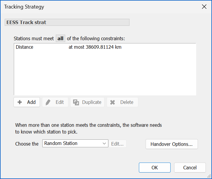
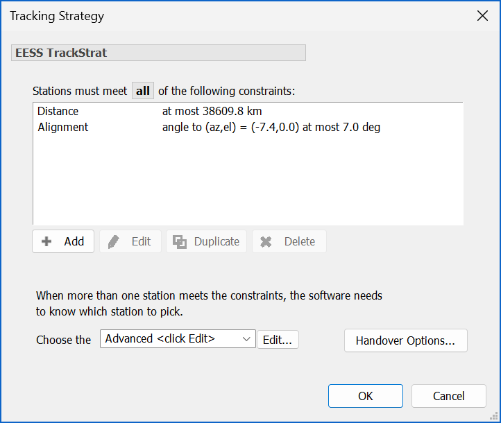
A key factor was to ensure the non-GSO UT only transmitted when within the cone of operation of the GSO satellite. In Visualyse Professional this can be done using a tracking strategy with distance constraint, as for circular orbit non-GSO UT that will be a constant, as shown in the figure below:
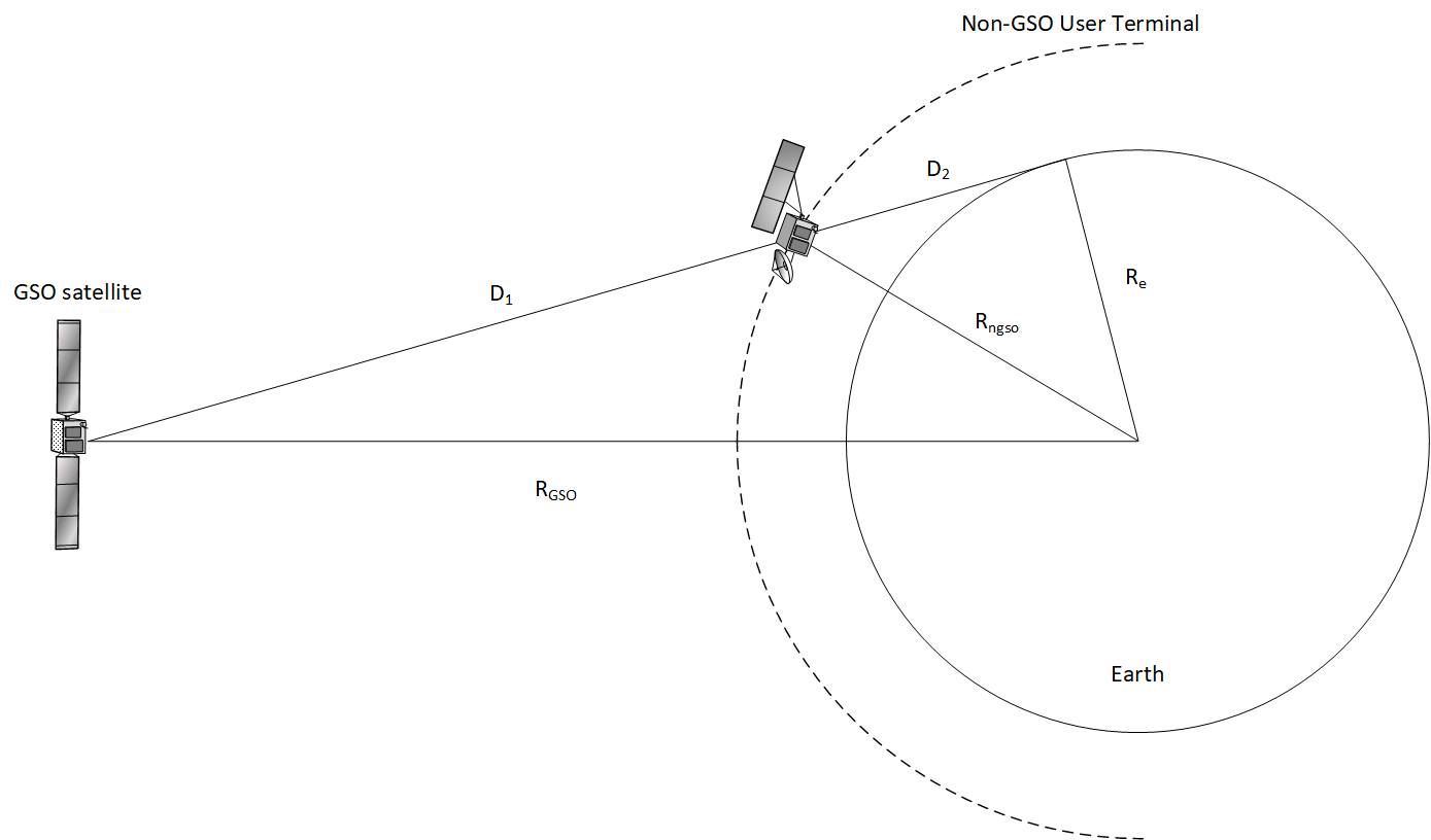
The distance, , can be calculated using:
This distance can then be entered in the tracking strategy as in the dialog below:
More advanced tracking strategies could be used to select specific locations. For example, one such method priorities those non-GSO UT that are at specified (azimuth, elevations) as seen by the GSO satellite.
It could also be useful to consider how to model the overall interference environment. For example:
- How many non-GSO UTs would operate co-frequency simultaneously?
- What would be the separation in distance between any two co-frequency non-GSO UTs?
- What areas of geographic coverage would be typical for non-GSO UTs operating to GSO satellites?
- What traffic profiles and data requirements could be used to model non-GSO UTs?
Note that polar regions would require operation to non-GSO satellites given the inability of GSO satellites to operate at latitudes over about 80° in latitude.
Non-GSO Victim System
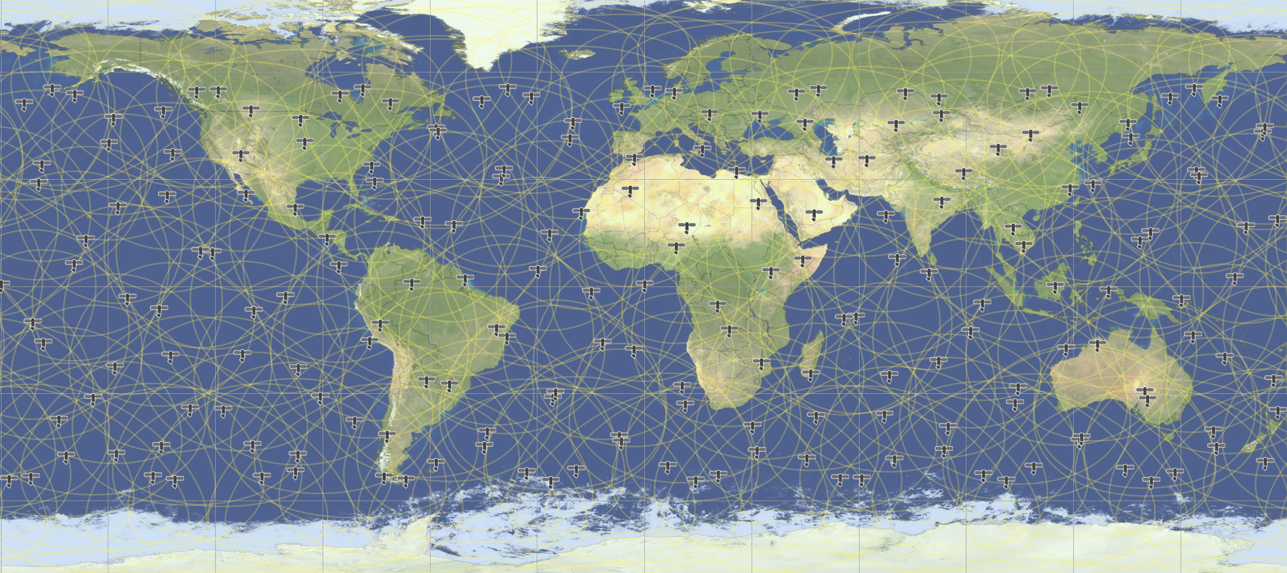
The non-GSO system was assumed to have the following parameters:
| Orbit height | 750 km |
| Number of satellite planes | 11 |
| Number of satellites/plane | 18 |
| Phase between planes | 4.5° |
| Orbit inclination | 55° |
| Spot beams | Tracking |
| Beam peak gain | 30 dBi |
| Beamwidth | 5° |
| Gain pattern | Rec. ITU-R S.672 Ls = -25 dB |
This constellation is shown in the figure below:
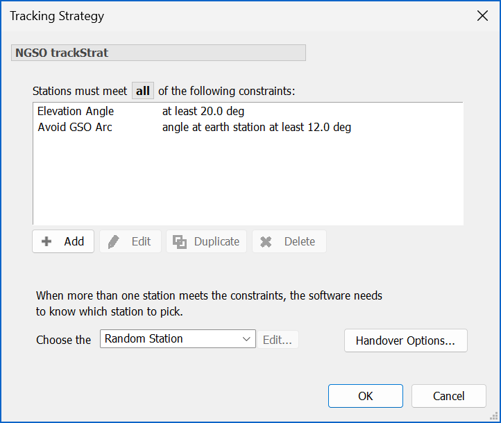
The study considered an UL at 18.1 GHz from an ES at a (51.5°N, 0.0°E) with the following tracking strategy:
The metric used in the study was the I/N from the non-GSO UT into the non-GSO victim system. Other metrics could be considered, including C/(N+I) and unavailability, and when modelling multiple links, statistics for the worst link, the average link or all links.
Overall Simulation
The final simulation is shown in the figure below:
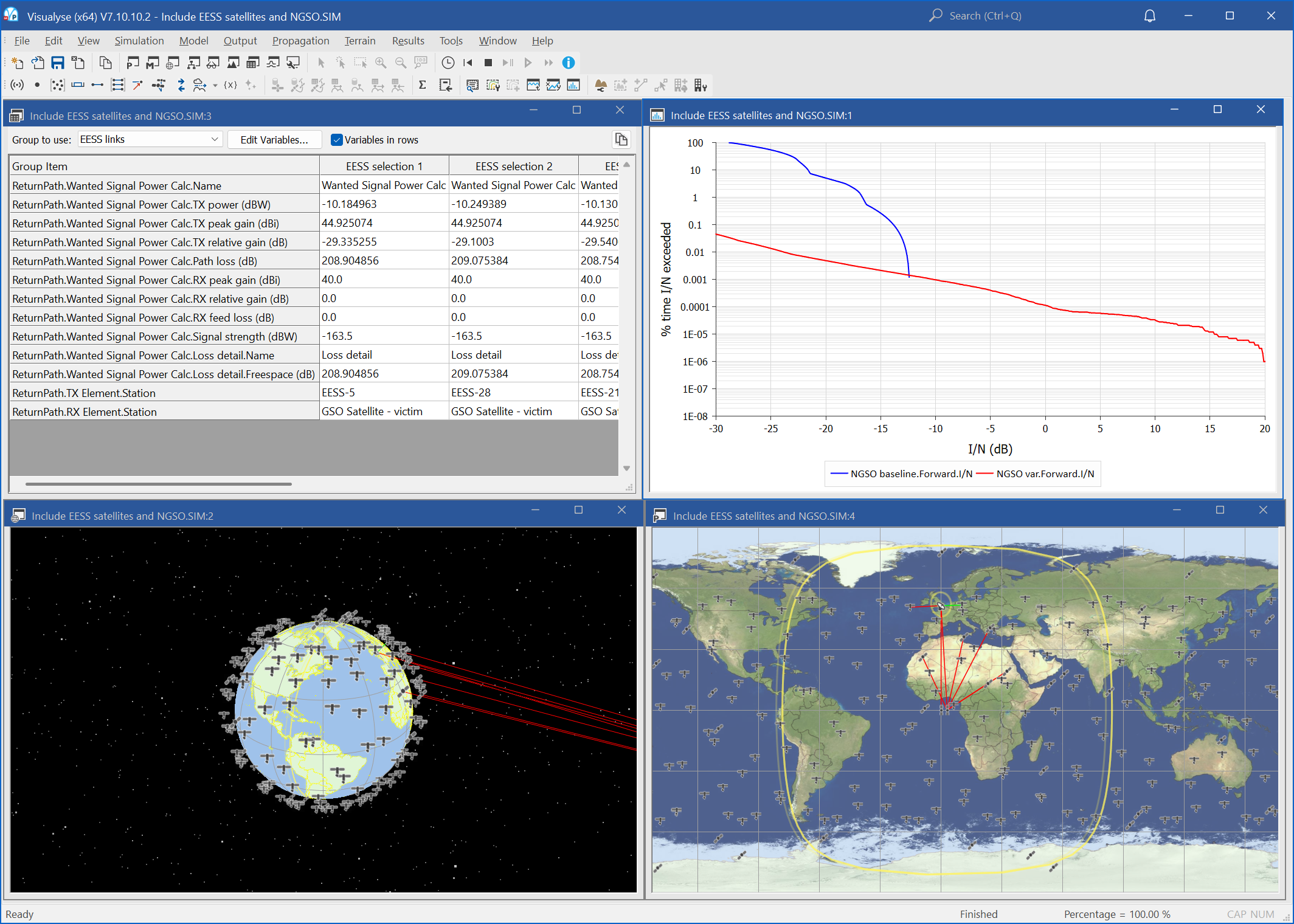
Because the key interference path involved non-GSO to non-GSO satellite dynamics, a small time step of 0.2 seconds was required.
A key result was the complimentary cumulative distribution functions of the interference. Two cases were considered:
- Interference into the non-GSO victim system from a GSO ES co-located with the non-GSO ES
- Interference into the non-GSO victim system from a set of non-GSO UTs
The plots are shown below:
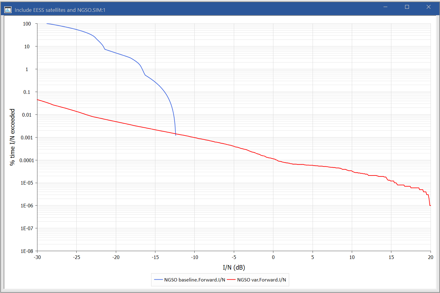
It can be seen that the non-GSO UT causes significantly higher interference into the non-GSO victim system (the red line) than from the GSO ES (blue line), but only for short periods of time.
Note that the baseline I/N could have been up to 15 dB higher if the non-GSO satellite had been in the main beam of the GSO ES.
The main reason for a higher level of interference for the non-GSO UT case relates to the reduced path separation:
Distance to GSO ES: at least 750 km
Distance to non-GSO UT: potentially 50 km
This reduction in path length leads to an increase in interference of . This is likely to be close to the maximum increase for satellites at this altitude as likely there'll be a limit in how close orbits will be permitted for space traffic management reasons.
Another factor was that this scenario allowed the non-GSO satellite to be in the main beam of the non-GSO UT.
There are additional factors that would require further study, such as the impact in aggregation and geometry (e.g. latitude of non-GSO ES).
Developing the Simulation
This is a baseline simulation and further analysis could include mitigation methods to protect the non-GSO victim system, such as exclusion distances and geometries. This could lead to further analysis of the impact in terms of the service that could be provided and the impact of diversity.
Other scenarios could model the reverse case, namely:
- Interferer: Non-GSO UT communicating with a non-GSO constellation
- Victim: GSO satellite network.
Further analysis could consider one non-GSO constellation communicating with the non-GSO UT interfering into another non-GSO constellation.
Advanced Simulations
Additional features could be studied. For example, Visualyse Professional has the ability to model both co-frequency and also non-co-frequency scenarios, as mentioned in recognizing e) of Resolution 773.
Furthermore, the Visualyse Interplanetary tool discussed in another document has the ability to model the impact of Doppler shift on wanted and interfering paths.
Sharing with Fixed Service
Similar analysis could be done with a victim fixed service (FS) link. The FS link could be defined to be:
- Generic, using parameters from Recommendation ITU-R F.758, which uses a number of other Recommendations, including the gain pattern in Recommendation ITU-R F.699 or F.1245
- Specific, using parameters imported from the ITU’s Terrestrial IFIC database.
Visualyse Professional can be used to analyse either of these approaches. The figure below shows the dialog that can be used to import from the Terrestrial IFIC:
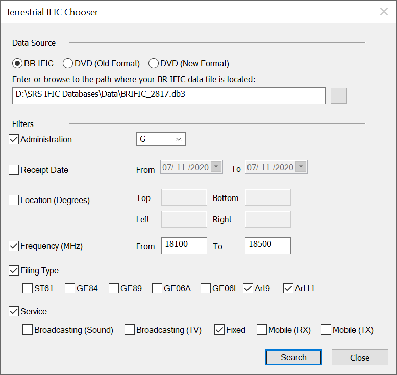
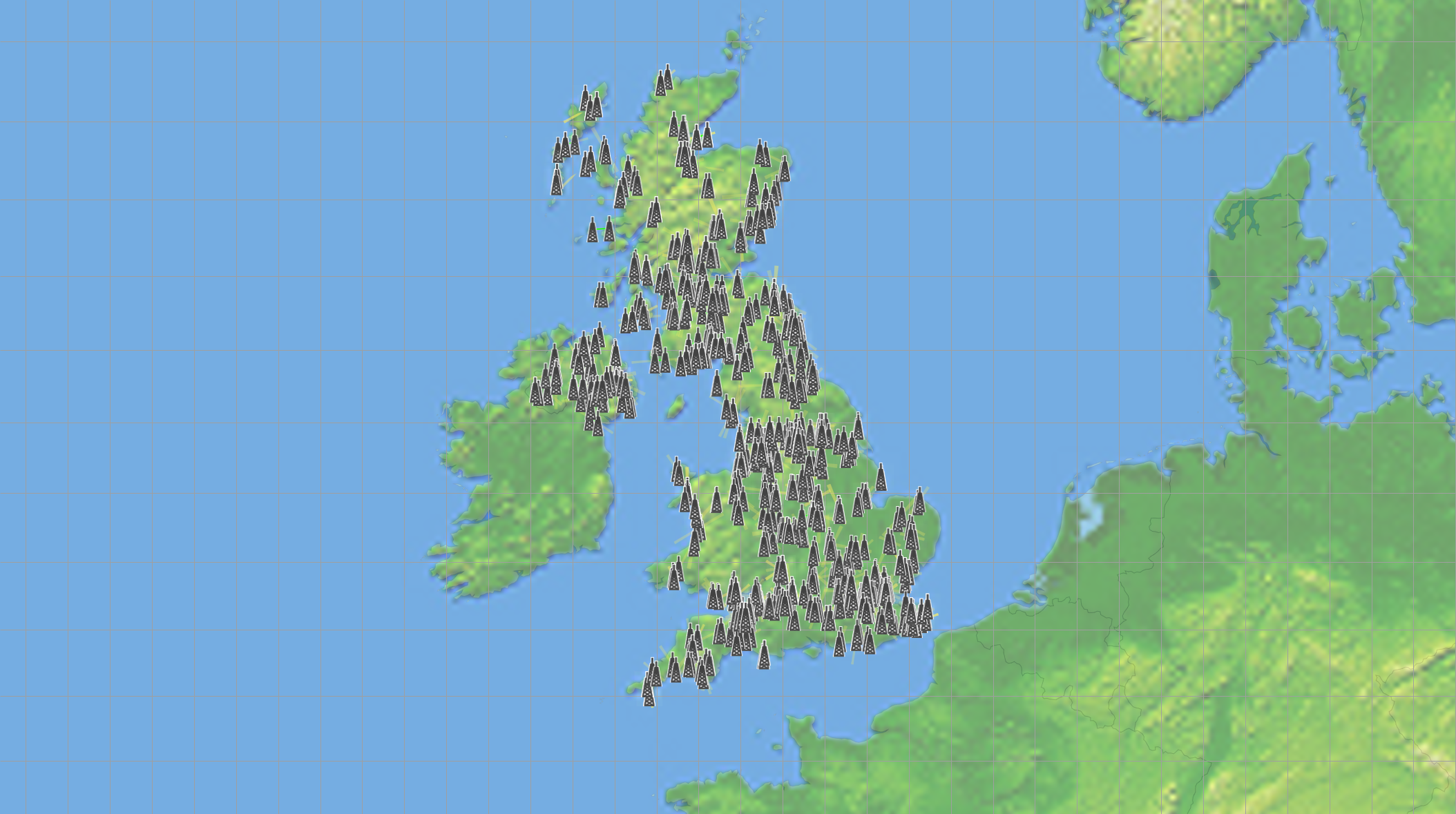
This query would import 488 point to point fixed links, as shown in the figure below:
Sharing with HAPS
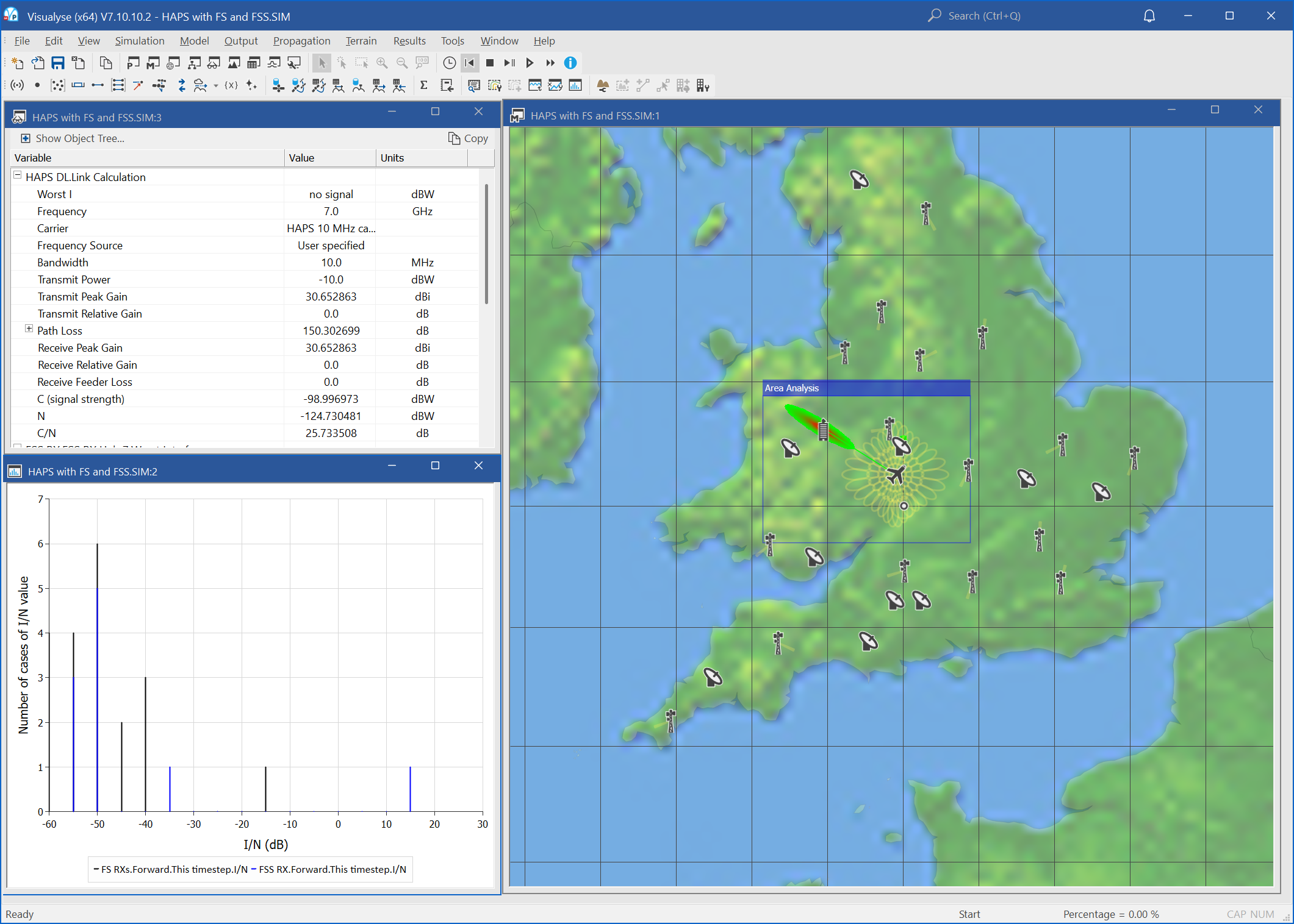
Visualyse Professional can also be used to model systems operating within the High Altitude Platform Service (HAPS), such as shown in the figure below:
Sharing with Other Services
The flexibility of Visualyse Professional means it could be used to analyse a wide range of services, from mobile to radiolocation.
