
22
Jul
Abstract
Discussions in the space industry this summer seem dominated by developments in direct to device (D2D) communications, led by operators such as SpaceX and AST Mobile. Questions have been about the service that can be provided, the impact of orbit height, and the need for large numbers and/or size of satellites. This paper provides a top-level analysis based upon the uplink link budgets and visibility statistics derived using the Visualyse Professional tool.
D2D Uplink Scenario
While the previous paper focused on the D2D downlink, analysing the PFD and sharing issues, this paper undertakes an uplink (UL) analysis using simplified parameters of the scenario in this figure:

A user equipment (UE) is transmitting in the UL direction at the edge of a beam from a D2D satellite. This direction of a D2D system is particularly constrained given the low gain of the handset (possibly negative taking into account propagation path losses) and restrictions on its transmit power. Typically, user equipment (UE) such as handsets are limited to a maximum transit power of 23 dBm or -7 dBW which constrains the service that can be provided.
The link budget can be derived based upon a set of parameters including:
- Satellite orbit height
- Satellite receive antenna peak gain
- Elevation angle of the satellite as seen by the UE
- Service to be provided.
In the analysis, the first two of these parameters were taken from an ITU-R filing, while the last two were considered variables to modify. Two services were considered:
- Messaging, assumed to require a single resource block
- Video, assumed to require 12 resource blocks.
A resource block can be considered a carrier with bandwidth 180 kHz within a 200 kHz channel.
Additionally, the following generic assumptions were made:
| UE aggregate transmit gain (dBi) | -8 |
| Edge of beam relative gain at satellite (dB) | -5 |
| Satellite antenna type | Phased array |
| Satellite receive temperature (K) | 300 |
| Intra-system interference margin (dB) | 2 |
These parameters were based upon Starlink's D2D FCC application in document "Application D2D Narrative 07-12-24.pdf". Phased array antennas were assumed to have peak gain that varied according to the angle from sub-satellite point using the cos rule. The link parameters were taken from ITU filings with frequency = 1.99 GHz.
MARS-ULS: Impact of Orbit Height
The following parameters were taken from the filing MARS-ULS/122545220 as used by SpaceX:
- Orbit height (low): 340 km
- Orbit height (high): 614 km
- Satellite peak gain: 34.8 dBi
Using the parameters above, C/(N+I) vs elevation angle calculations were undertaken the two orbit heights for the two types of service, as shown in the figure below:

The following can be seen:
- The UL C/(N+I) has little margin for additional losses, such as clutter or indoor to outdoor loss, limiting the locations that these services that can be provided
- The UL C/(N+I) decreases as the elevation angle decreases
- The UL C/(N+I)s for a system with orbit height of 340 km are better at all elevation angles than those for an orbit height of 614 km
- The UL C/(N+I) of a video service for a system with an orbit height of 614 km is always below zero even at an elevation angle of 90
- The UL C/(N+I) of a video service for a system with an orbit height of 340 km is only above zero for elevation angles above about 65.
- The UL C/(N+I) of a messaging system is above zero even for low elevation angles for both orbit heights.
The impact of elevation angle on the quality of service that can be provided is more apparent if the C/(N+I)s are converted into throughputs using Recommendation ITU-R S.2131 as shown in the following figure:

The following are observed:
- There is a significantly better throughput for video services for a system operating at a height of 340 km compared to one at a height of 614 km
- The ability to provide a video service is limited to only very high elevation angles, in particular for a system operating at a height of 614 km
- For a system operating at a height of 340 km, there is the ability to provide a video service above about an elevation angle of about 60.
Note that another advantage of a lower altitude satellite is that for a given antenna beamwidth, the footprint of the beam on the ground is smaller, permitting a higher frequency re-use and also higher traffic densities and hence system capacity. There are also likely to be lower latency. A disadvantage with a lower orbit height is that more satellites are required to provide continuous coverage, as analysed in the following section
Visibility and Coverage Analysis
The MARS-ULS constellation was analysed, which comprises 29,988 satellites at a range of heights from 340km to 614 km. The constellation is shown in the figure below:
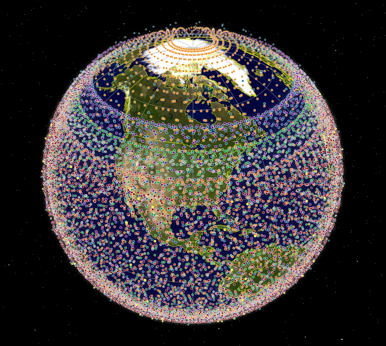
Of the total "only" 19,440 of these satellites were at an altitude around 340 - 360 km, sometimes described as very low Earth orbit or VLEO.
For the satellites in this height range, an analysis was undertaken in Visualyse Professional on the minimum number of satellites that would appear to be above a set of minimum elevation angles (MEAs). The results for a test point at (latitude, longitude) = (40N, 100E) are shown in the table below:
| Minimum elevation angle | Minimum number of satellites |
|---|---|
| 0 | 656 |
| 10 | 257 |
| 20 | 113 |
| 30 | 46 |
| 40 | 21 |
| 50 | 7 |
| 60 | 2 |
| 70 | 0 |
| 80 | 0 |
It can be seen that it can only be ensured that this at least one satellite visible at all times for a MEA of 60. This is consistent with the link budget analysis above that shows that an elevation angle of 60 is required to provide a video service to a handheld UE.
The number of satellites able to provide video DVD services could be supplemented by having two MEAs:
- Orbit heights 340 - 360 km, MEA = 60
- Orbit heights 525 - 614 km, MEA = 75
This tracking strategy resulted in an improvement in the maximum number of available satellites from 7 to 11.
Hence it appears that the constellation allows the provision of high capacity D2D services including UL of video to satellites in VLEO. This constellation design considers:
- Height: a constellation operating in VLEO is required to close the UL link budgets for demanding services such as video
- Size: a constellation with around many thousands of satellites is required to provide continuous service at the higher elevation angles required to provide demanding services like video.
MICRONSAT: Impact of Satellite Antenna Gain
But is it essential to operate at VLEO? Could a D2D constellation provide video for the UL direction while operating at a higher altitude? To answer this question, the following parameters were taken from the filing MICRONSAT-2/123520009 as used by AST:
- Orbit height (high): 510 km
- Satellite peak gain: 46 dBi
These were compared against the MARS-ULS low orbit configuration from the previous section. As well as operating at a higher orbit, another key difference between the two systems is that MICRONSAT has a greater satellite peak gain. Documents submitted to the FCC suggest that the phased array antenna at the satellite could have over 9,000 elements, which would require a larger satellite.
The C/(N+I) vs elevation angle calculations were undertaken the two filings, MARS-ULS and MICRONSAT-2 for the two types of service, and are shown in the figure below:

It can be seen that even though the MICRONSAT-2 satellites are at a higher orbit than the VLEO satellites of the MARS-ULS constellation, the C/(N+I)s are better due to the greater satellite antenna peak gain. This is reflected in the throughput calculations in the figure below:

With the greater satellite antenna peak gain, the MICRONSAT-2 system could provide video UL services to lower elevation angles, which allows for a smaller constellation of satellites.
Conclusion
This paper has shown how constraints on the UL link budget can drive non-GSO satellite operators to lower orbits and larger constellations. An example was given on how the MARS-ULS filing parameters are consistent with the need to be able to provide a high data rate service, potentially including video, on a continuous basis to low gain UEs.
As a comparison, the MICRONSAT-2 filing allows a similar service to be provided by a smaller constellation through use of a larger antenna with greater peak gain.
More detailed analysis could be undertaken in Visualyse Professional to model services, throughputs and capacity in both the downlink and uplink directions, considering intra-system interference and the need to meet PFD limits, both co-frequency and non-co-frequency, on the ground.